Shapez Make Anything Machines
I you haven’t heard of it, Shapez is a “a game about building factories to automate the creation and processing of increasingly complex shapes across an infinitely expanding map”.
It’s like Factorio, but easier for simpletons like me to understand.
There’s no “combat” either.
One of the cool things (and the point of this post) is that the game provides a way to automate the entire build process.
I’m not going to go in depth about how the game works - just going to overview my MAM design - so if you don’t know how to play the game, go play it!
Overview
I had a number of iterations of the design, but from the get go the basic design has been the same:
- Each “layer machine” creates a single complete layer
- 4 “layer machines” combine to make the full shape
- Color each quadrant separately (mostly)
- Merge quadrants together in a way that handles missing corners
- Merge layers together in a way that handles missing layers (but not overhangs)
- Try to make the design as spatially small
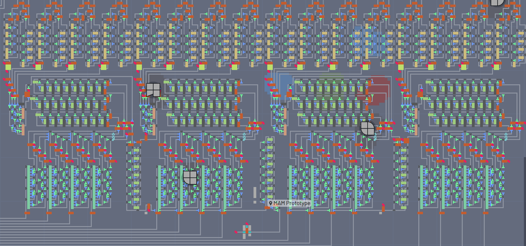
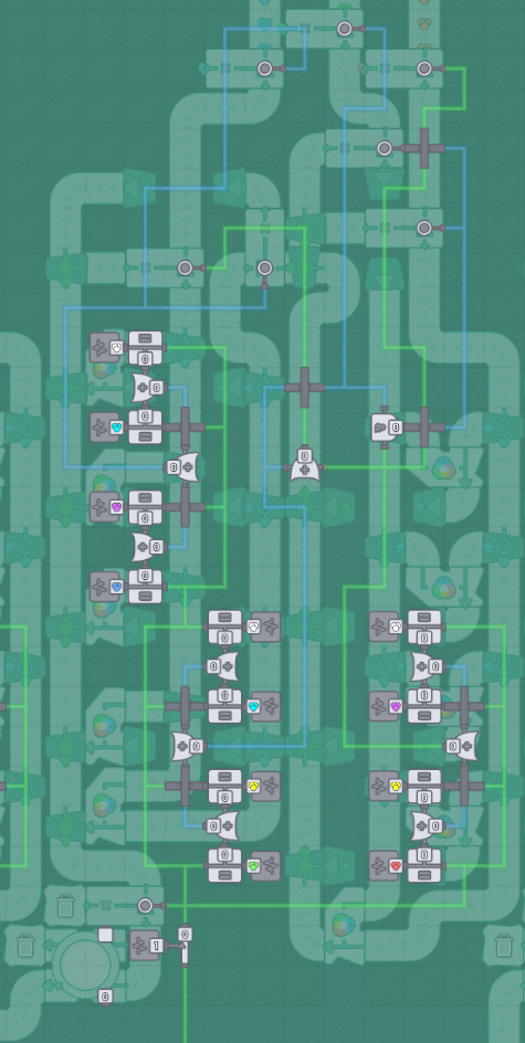
Without further ado, an overview picture:
Buildings:
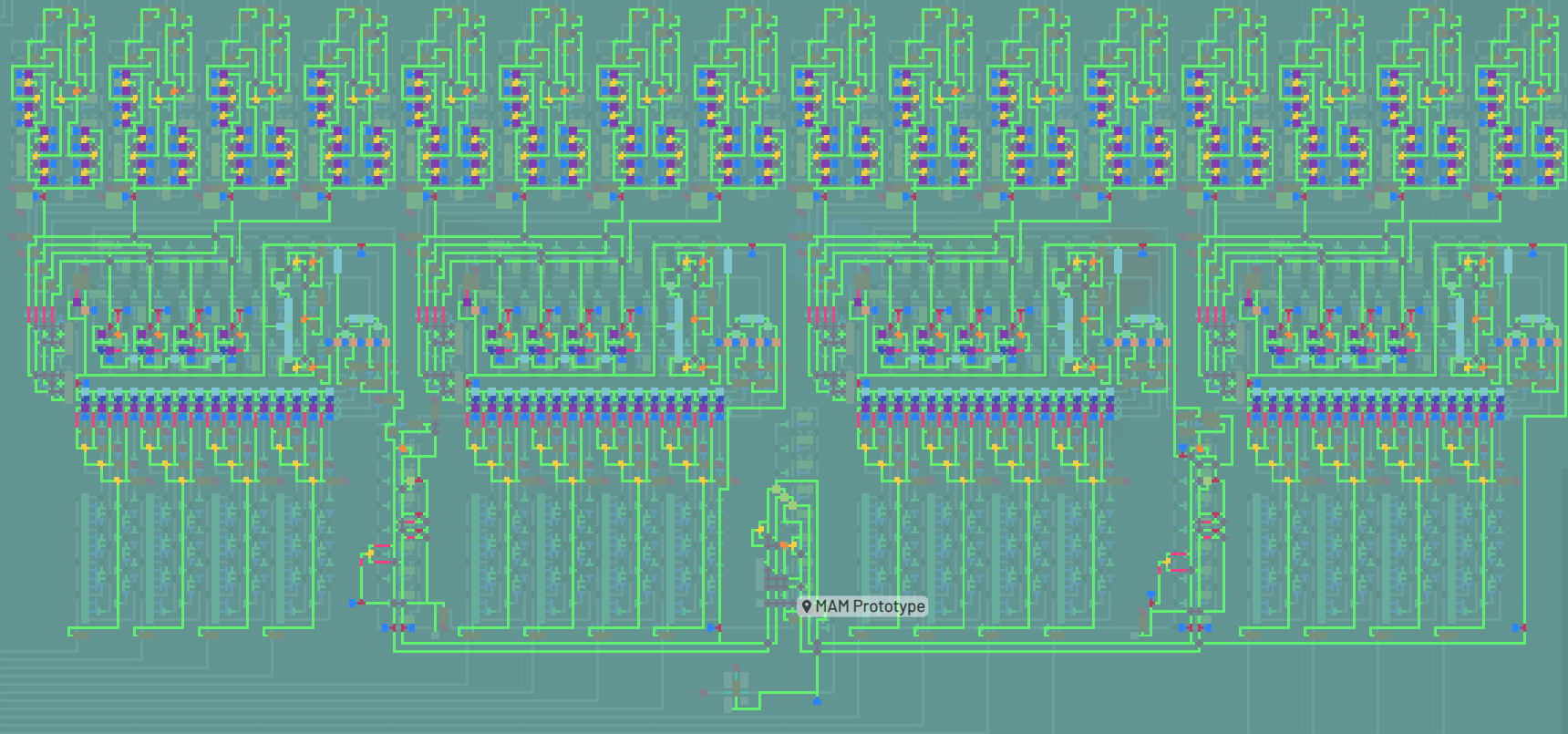
Wires:
Common Patterns
Discard (Unexpected) Filter
At various points, the belt goes through a filter that has a trash on the secondary output.
This is used to discard items that are unexpected.
THe unexpected items come from when the machine is switching from one desired item to another: the processing doesn’t all switch instantly or at the same time, so there’s some “crap” that happens in the middle that needs to be thrown away.
The machine will work fine without these filters, it’ll just process more junk than it needs to when switching, thus increasing the latency of switching.
Bypass Filter
Some stages of processing need to be skipped.
For example, when combining two quadrants, layers, or colors, if one of the inputs is not present the other one must bypass the processing entirely.
“Double NOT”
The “double NOT” is simply two NOT operators in a row on the wires layer.
This has a number of effects.
Firstly, it forces the output to be boolean: either 0 or 1.
The other effect has to do with the “unconnected” wire state (aka ∅).
This is not 0 but after going through the “double NOT”, it comes out 0 on the other side.
This is necessary because many wires-layer processing does weird shit with ∅.
This is especially noticeable when given as an input to a belt filter: the filter simply stops operating all together!
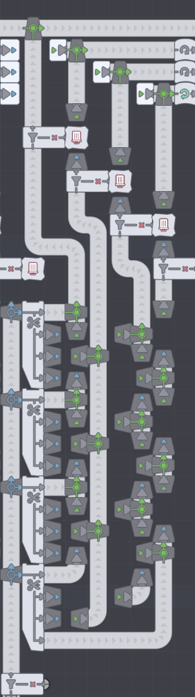
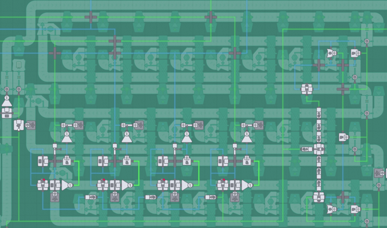
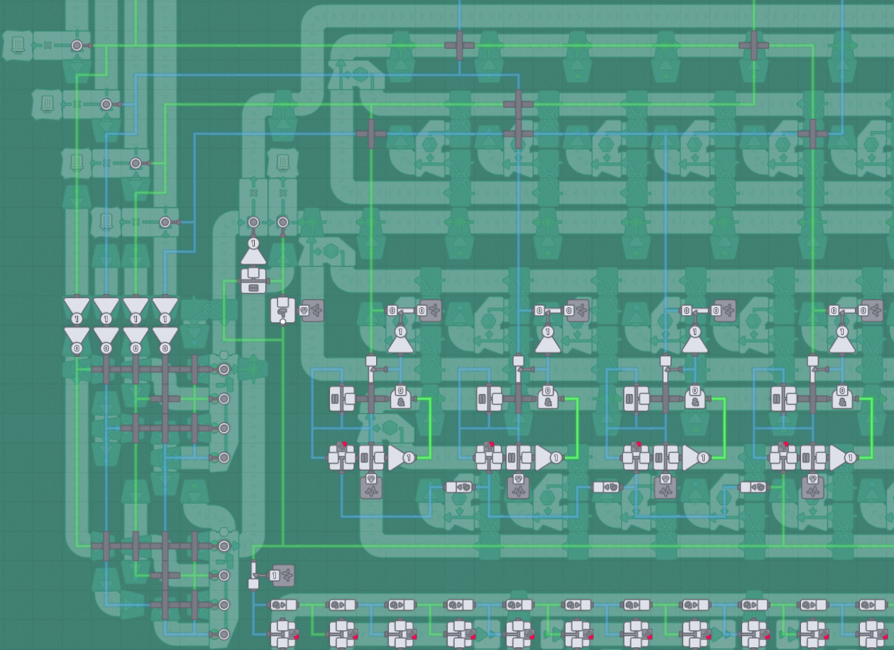
Layer Machine
Zoomed in on a single Layer Machine and modules labeled:
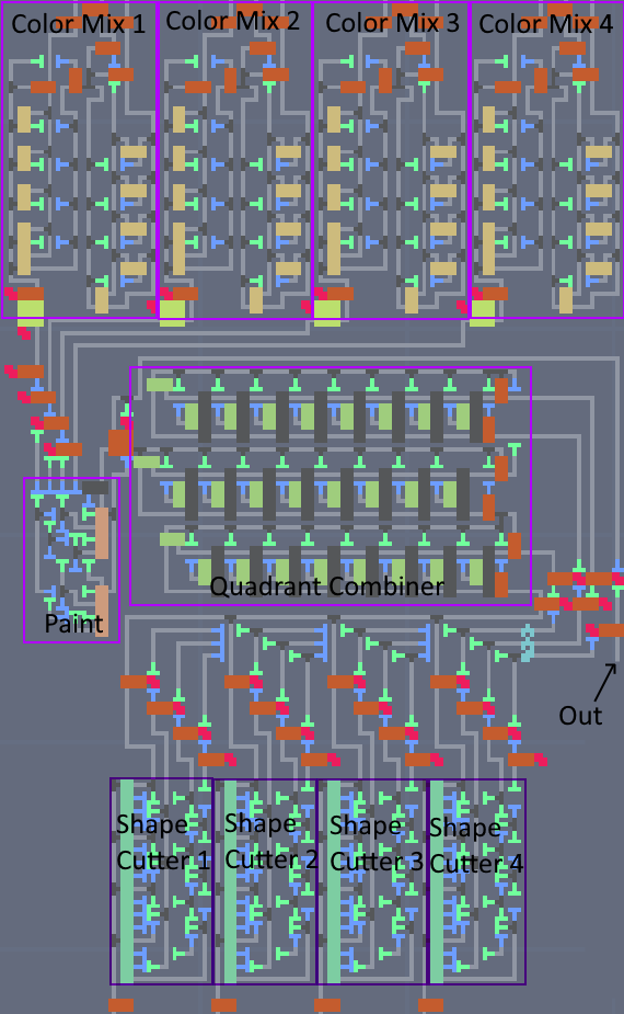
Primary color resources come in the top. Shape resources come in the bottom.
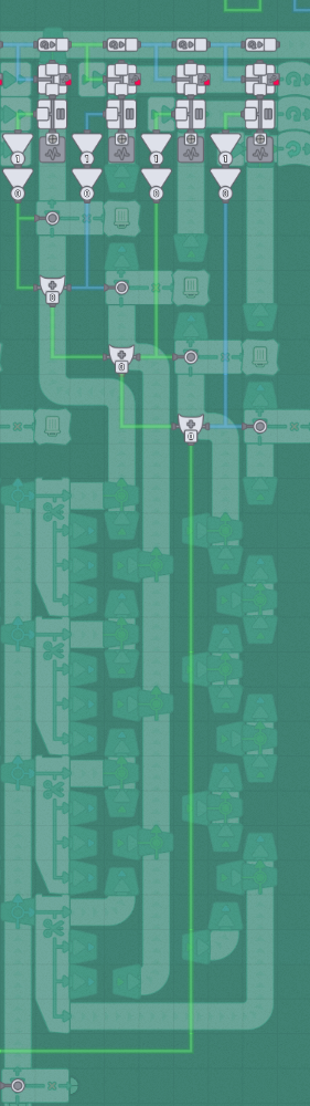
Color Mixer
Primary colors enter at the top. On the wires layer, the desired color enters at the bottom.
In wires, there’s a bunch of comparators to see if the desired color is one of 4 options:
the primary color itself, each of the secondary colors that use this primary, or white:
If the primary color is needed (either on its own or to combine with others), it turns on the filter nearest the color input.
If both green and red are required, the two filters turn on to send them through the column of mixers on the right, otherwise they “bypass” to the left.
On that bypass path, there’s another bypass that sends the Red/Green/Yellow either to the 2nd set of mixers (if blue is also required) or to another bypass path (if wer’re done).
On the blue path, there’s a filter that sends blue into the 2nd set of mixers (if Red or Green is active) or on a bypass to the output (if output is Blue).
The final color output goes through a filter to weed out undesired colors (such as when switching) and finally an “overflow dump” (a storage with a trash on the secondary output).
These two steps are to reduce the latency incurred when the desired pattern changes.
Finally, the Color Mixer is tiled 4 times per Layer Machine - one for each quadrant.
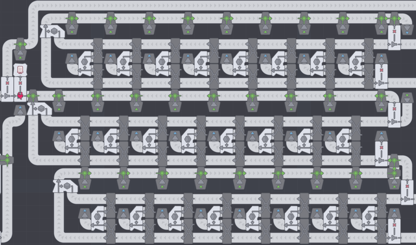
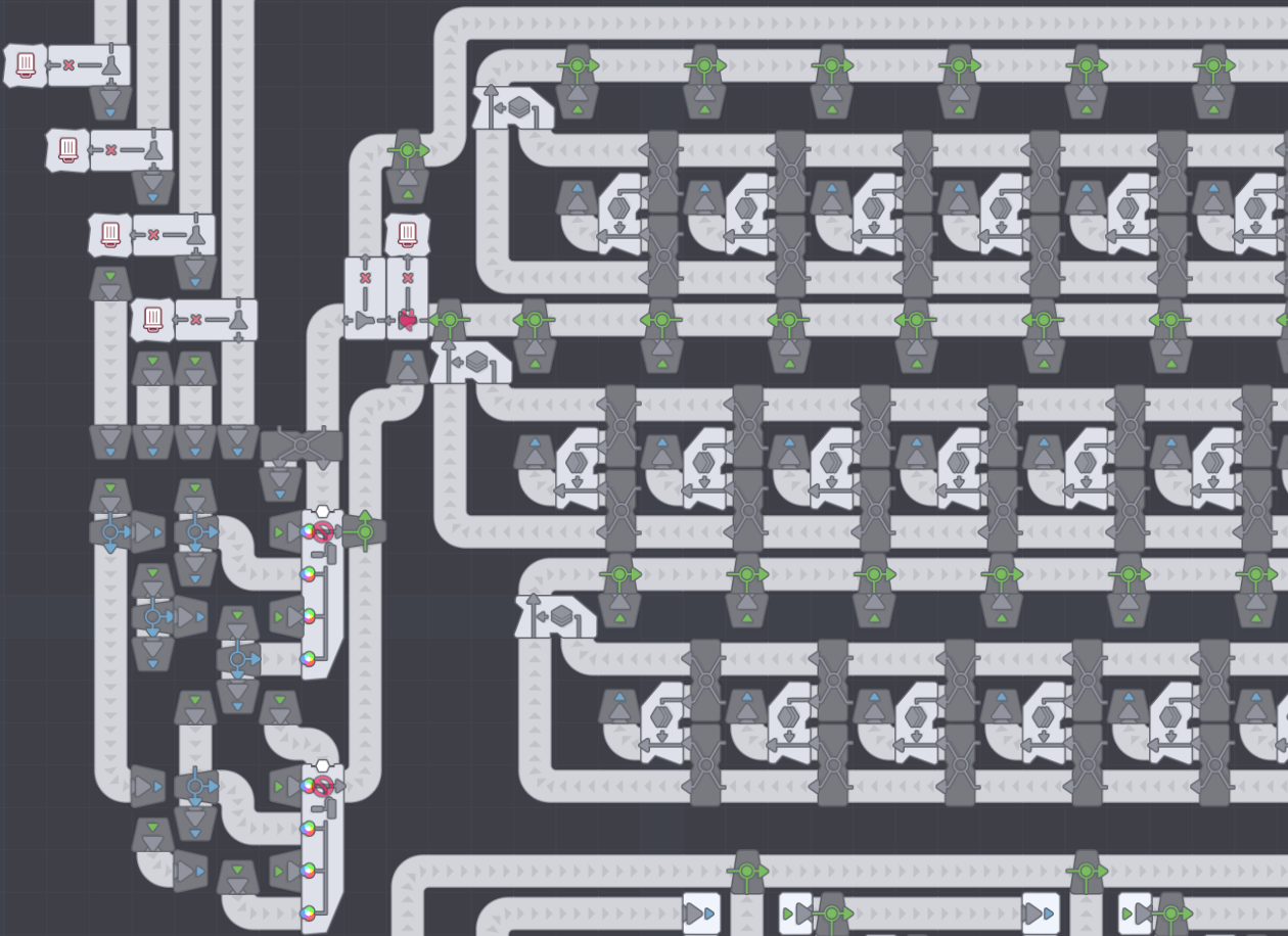
Shape Cutter
The shape cutter is quite simple: take a shape and cut it up into 4 lanes - one for each quadrant.
There is a filter on the end of each of the 4 lanes - if that shape is needed for the given quadrant output it, otherwise throw it away.
The trashing is necessary otherwise unused quadrants will clog up and stop the quad cutter from operating.
In order to reduce unnecessary work, if none of the 4 quadrants are needed, a filter on the input halts the flow.
Finally, the Shape Cutter is tiled 4 times per Layer Machine - one for each possible shape (Circle, Rectangle, Windmill, Star).
Shape Cutter to Quad Combiner
In between these two steps is a small amount of processing:
First, some of the belts get rotated. This essentially “reorders” the belts to match the wires layer that distributes to all 16 comparators in the Shape Cutter section.
Then there’s a set of filters that discard anything but the expected quadrant shape (this helps latency when switching).
Quadrant Combiner
This section is pretty straightforward - combine the (up to) 4 quadrants into a single shape.
The trick comes in the bypasses.
There are 3 sets of mergers. The first two sets each combine 2 quadrants while the third combines the result of the first two.
For all 3 of them, if either input is missing, bypass the mergers and send both to the next step (one of them will be empty though, obviously).
Note that the left 2/3rds of the wires layer shown is for the Paint stage, not the Quadrant Combiner.
Finally, at the end there is a filter that discards any unexpected shapes (which only happens when switching).
Paint
The painting stage is one that changed the most over all my iterations as well as the one that uses the most wires logic.
The original design had 4 sets of simple painters (one for each quadrant) that sat between the Shape Cutter and the Quad Combiner.
This took up more space than the Quad Combiner!
Once the Quad Painter is unlocked, it only takes 2 of them to match the belt speed and it takes up drastically much less space.
The wires layer spills over into the Quad Combiner (which works out because the QC doesn’t have much for wires itself).
The first step is to take the desired shape and remove it’s color - this is achieved using a Virtual Painter with a “Gray” paint color.
This “uncolored shape” is used to as a discard filter at the end of the Quad Combiner.
Immediately after that is another bypass filter - if the “uncolored shape” equals the desired shape then none of the painting needs to happen at the painters are bypassed.
The other wires logic is simply looking at the quadrant’s color and if it’s equal to itself (ie, NOT ∅) AND it’s not equal to gray, pass it through. Otherwise put a 0 on the wire.
These 4 “desired color” outputs feed two things: one set goes up to the Color Mixers to produce the desired colors and the other set goes through “double NOT”s and feed the 4 inputs of the Quad Painter.
Layer Combine
In between the 1st and 2nd Layer Machines (as well as between the 3rd and 4th) is a merger column.
This is identical to one of the three merger rows in the Quad Combiner, except this time we’re merging layers instead of quadrants.
Somewhere on the belt path between the LM output and the Layer Combiner input is a discard filter.
If one of the layers is missing, the present one bypasses the mergers.
Final Layer Combine
In the very middle of the MAM is another merger column (just like the Layer Combine) that merges the “top half” layers with the “bottom half” layers.
As usual there are discard filters between the two stages over layer combining.
This represents the final assembly stage and the final desired shape is presented at the output.
There is a final discard filter to ensure that only the desired shape exits the MAM and any intermediate switching artifacts are discarded.
The 4 Layer Machines are laid out left-to-right (in the shown pictures).
The left-most LM does the top-most layer of the final shape, while the right-most LM does the bottom-most layer of the final shape.
This wasn’t chosen so much as it’s the order that lines up with the Virtual Layer Unstacker output mechanics as well as the order of the Merger in the Layer Combiners.
Optimization Thoughts
I had a lot of fun iterating this design to make it smaller and to reduce the latency.
The two biggest things that contribute to latency is “invalid” shapes/colors/layers and distance from the Hub.
The “invalid” items are filtered out with Discard Filters so that the junk can be filtered out as soon as possible before it clogs up more processing.
I haven’t gotten around to it but “flush” gates at the end of processing stacks could be added to drain the junk when switching happens.
I’ve tried a couple things but they all take up significant space and I haven’t been able to make them fit while being worthwhile - for now I just take the latency hit when switching somethings.
Distance from the hub is another one - the raw (shape and color) input belt lengths do not matter (since their contents never change), so MAM placement should be all about optimizing and reducing the output belt length.
Bonus Designs
Discard Filter with Monitoring
This is a little pattern that builds on the Discard Filter to add a bunch of wires-layer monitoring. There are 3 points as well as 3 pieces of data at each of those points. Points:
- input
- discard output
- output Data:
- speed
- presence (are there items currently passing through this path)
- last item seen
None of this is strictly necessary, it’s just fun to look at sometimes.